English


In low-voltage power grids, circuit breakers are widely used for overload and short-circuit protection. However, if the circuit breaker is improperly selected, it may cause malfunction or refuse to operate, losing its protective function and reducing the reliability of the power supply. The general principles that need to be considered when designing and selecting circuit breakers are:
1. Have sufficient making and breaking capabilities;
2. Meet the requirements of system selective protection;
3. Reasonable price/performance ratio.
After determining the structure type of the circuit breaker first, then choose the electrical parameters. The so-called electrical parameter selection, in addition to the rated voltage, rated current and breaking capacity of the circuit breaker, an important issue is how to select the setting current and protection characteristics and coordination of the circuit breaker overcurrent release to achieve an ideal coordination. action.
1. General selection principles
This refers to the principles that must be followed when selecting any circuit breaker:
1. The rated operating voltage of the circuit breaker ≥ the rated voltage of the line
2. The rated current of the circuit breaker ≥ the calculated load current of the line.
3. The rated short-circuit breaking capacity of the circuit breaker ≥ the maximum short-circuit current that may occur in the line, generally calculated based on the effective value.
If the rated current of the selected circuit breaker meets the requirements, but the rated short-circuit breaking capacity is less than the maximum short-circuit current of the line at the installation point of the circuit breaker, the rated current of the selected circuit breaker must be increased, and the overcurrent release should be selected according to the load current of the line. rated current. If this does not meet your needs, you can consider the following three solutions:
① The cascade protection (or cascade protection) method is used, which uses the upper-level circuit breaker to act together with the circuit breaker to improve the short-circuit breaking capacity. When using this solution, the instantaneous current of the tripper of the upper-level circuit breaker needs to be set at about 80% of the rated short-circuit breaking capacity of the lower-level circuit breaker.
② Use a current-limiting circuit breaker.
③ Use circuit breaker and backup fuse. However, it should be noted that this gives up selective disconnection
4. The single-phase to ground short-circuit current at the end of the line is ≥ 1.25 times the instantaneous (or short delay) setting current of the trip unit of the circuit breaker.
This is especially important when the load current is small and the distribution lines are long. Because when the line is longer, the short-circuit current at the end is smaller, and the single-phase to ground short-circuit current is even smaller. The "single phase to ground" here refers to one phase to the ground in a three-phase three-wire system. Compared with a short circuit, the short-circuit current passes through the earth (the ground resistance is large), so the short-circuit current is small, sometimes smaller than the setting current of the over-current release, and the over-current release cannot be operated, so in single-phase ground Protection is lost in the event of a short circuit. In this case, if the above requirements cannot be met, special measures will need to be taken to solve the problem. Usually, there are three methods to protect one phase to ground fault: one is to install a current transformer on the neutral line, and the secondary side of the transformer is connected to a current relay. When a single phase to ground short circuit occurs, the relay operates to break the circuit breaker; the other is to It uses a line with a zero-sequence current transformer or a leakage relay, which has higher sensitivity. When using these two methods, the neutral point of the transformer should be connected. The third method is to use a circuit breaker with single-phase ground fault protection.
5. The rated voltage of the circuit breaker undervoltage release = the rated voltage of the line. Whether under-voltage protection is required should be determined according to the usage requirements. Not all circuit breakers need to be equipped with under-voltage releases. In some systems with poor power supply quality, the use of circuit breakers with undervoltage protection will often cause unwanted power outages due to voltage fluctuations. In this case, if an undervoltage release must be provided, appropriate delay should be considered.
6. If a circuit breaker with short delay is equipped with an undervoltage release, the undervoltage release must be delayed, and its delay time ≥ short circuit delay time.
7. The rated voltage of the shunt release of the circuit breaker = the control power supply voltage.
8. The rated working voltage of the electric transmission mechanism = the control power supply voltage.
9. Check the wiring direction of the circuit breaker. If the technical documents or terminals of the circuit breaker indicate that the wiring can only be entered from the top, then the wiring from the bottom cannot be used during installation. The bus coupler switch must use a circuit breaker that can be lowered into the line. In addition to the general selection principles, attention should be paid to the purpose of the circuit breaker. The selection characteristics of circuit breakers for power distribution and circuit breakers for motor protection should be considered separately.
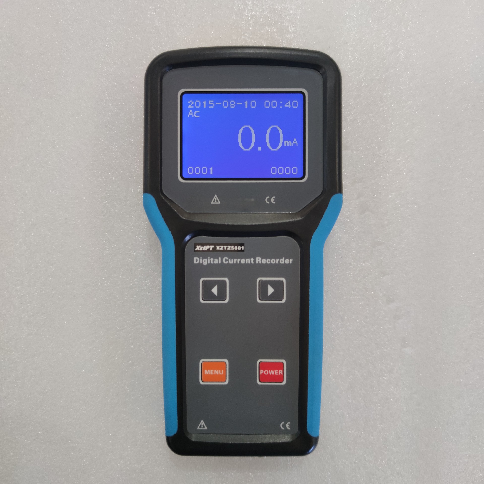
XZTZ5001 Transformer Core Grounding Current Tester
