1. Abnormal forms and treatment methods of transformer cooler
1. Main abnormal forms: Transformer cooling methods include oil-immersed air cooling, oil-immersed self-cooling, forced oil circulating air cooling, forced oil circulating water cooling, etc. Oil-immersed air cooling relies on hot oil self-circulation and dissipates heat through the radiator. ; Forced oil circulation air cooling uses a submersible oil pump to circulate the oil and dissipate heat through the radiator for cooling. The main fault forms of the forced oil circulation air cooling system of the transformer include: air-cooled AC power supply failure; fan motor thermal burnout; fan motor burnout, bearing damage, fan blade blade and oil pump failure.
2. Cooler abnormality and treatment:
(1) The cooler power supply disappears. Phenomenon: The alarm bell rings, and the main control panel sends out signals such as "main transformer cooler power failure". Depending on the cause of the failure, the signals sent are different. Treatment: The disappearance of the two sets of power supplies of the main transformer will cause the cooler to stop completely and the temperature of the transformer to continue to rise; if the station transformer fails and causes the cooler to stop completely, the power supply of the station transformer must be restored first and then dealt with item by item; if the station transformer fails, the power supply of the station transformer must be restored. If the electric panel power supply fuse is blown and the cooler is completely stopped, first check whether there is any fault in the power inlet part of the cooler control box. After troubleshooting, put each cooler selector switch to the "stop" position, and then force the If the power supply is successful, restore the operation of each group of coolers one by one; if not, carefully check whether there are any abnormalities in the power supply and the integrity of the cables from the station power supply to the cooler control box; if the power supply of the cooler control box is If the automatic switching circuit causes a total shutdown, the backup power supply must be manually turned on immediately and the operation of the cooler must be resumed immediately. If both the working and backup power supplies fail and it is difficult to handle, the dispatcher must be reported immediately and apply for dispatching to transfer the load. After the failure occurs, the transformer must be strengthened. Oil temperature monitoring to prevent excessive oil temperature from burning the transformer or shortening its service life.
(2) Group cooler failure: Phenomenon: the alarm bell rings, the main control panel sends out signals such as "cooler failure" or "standby cooler input", on-site inspection shows abnormal conditions such as thermal coupling action of the cooler, abnormal operating sound of the motor, etc. . Treatment: First check if a spare cooler is put in, then put the control switch of the faulty cooler to the "stop" position, and then adjust the operation of each group of coolers according to load, temperature, etc. If no cooler in the "working" position is found to be out of service on site, check the operation of the oil flow relay of each group of coolers. If there is any failure, the control switch of the cooler of the group should be placed in the "stop" position, the backup cooler should return to shutdown, and then the cooler of the group should be shut down and reported to the relevant department for processing. If no abnormal conditions are found during on-site inspection after the standby cooler is started, the "working" coolers can be stopped one by one for inspection. When a certain cooler is out of operation and the backup cooler returns, it can be judged that the group of coolers is faulty, and then the group of coolers is shut down.
2. Analysis and treatment methods of tripping causes of transformer cooler group
1. Analysis of tripping causes: (1) The wind angle of the cooler or the oil pump motor is overloaded, and the thermal relay operates, causing the magnetic switch of the cooler group to lose excitation and trip. It should be that the fan blades are stuck against the shell, or the fan or oil pump motor bearings are damaged, causing it to be overloaded. (2) The operating current of the cooler group or a certain fan oil pump motor increases due to phase loss, causing the thermal relay to operate. (3) The thermal relay is subject to extreme heat, etc., and the temperature rises and malfunctions. (4) Thermal relay contacts are damaged due to vibration or dirt. Poor contact may cause malfunction due to heat generation. (5) The circuit insulation is damaged.
2. Treatment method: (1) First change the automatically put-in standby cooler group to the "Run" position. Determine whether the thermal relay is tripping or the air switch is tripping. Thermal relays are generally used for overload and phase loss protection, but cannot protect against short circuit faults. Air switches are usually used to protect against short circuit faults. (2) If the air switch trips, check whether there is a short circuit fault point in the circuit. Check for short circuit faults in the circuit, mainly checking whether there are any problems with the components and motor in the control box. During processing, if it trips again during trial operation, the fault is not eliminated. (3) If the thermal relay operates and causes the cooler group to trip, you can determine whether the oil pump motor or a certain fan motor is overloaded when the thermal relay position is restored. Put the cooler group back into operation for a short time, observe whether the overloaded fan and oil pump motors are normal, and listen to their sounds to identify faults and deal with them respectively.
If the sound of the submersible oil pump is abnormal, the cooler group cannot be put back into operation and should be handled by maintenance personnel. In the fan motor, if there is abnormal sound, serious friction, or the fan blades hit the shell or cannot rotate, etc., you can remove the terminal wires of the faulty fan motor in the cooler group control box and restore the position of the thermal relay. After the trial operation is normal, put this group of coolers into operation or standby position. The maintenance personnel shall inspect the motor and put it into normal operation after treatment. If the entire cooler or individual fan motors do not start, check the three-phase voltage status, whether there is a phase loss, and whether the control circuit fuse is blown or has poor contact. The cooler group is overloaded and the thermal relay trips. Stop for a while and then restore the thermal relay position. If it trips again after being put back into operation, do not increase the operating current of the thermal relay to prevent it from burning the motor due to failure.
3. Transformer cooler full stop troubleshooting method
While the transformer is in operation, the coolers are all shut down. The fault may be caused by a cooling power supply failure and a power switching circuit failure, causing the cooler to completely stop working. If not handled in time, the transformer may automatically trip and cause a power outage. When the "cooler full stop" signal is reported, the fault should be judged according to other signals reported by the cooler control circuit, the position of the voltage relay contact of the cooling power supply, the position of the two main contactors of the cooling power supply, etc.
There are two cases of cooler full stop failure. One is "cooler full stop", "cooling power supply I failure" and "cooling power supply II failure". The second is to report two signals: "cooler full stop" and "cooling power supply failure". The nature and scope of the fault in the two situations are different, and the handling methods are different.
1. The first processing method: "cooler full stop", "cooling power supply I failure" and "cooling power supply II failure" are all reported. It indicates that the power switching has taken place, but the switching was unsuccessful. A short circuit fault occurred in the circuit below the main contactor contact of the cooling power supply. (1) Immediately replace the two cooling power fuses. At the same time, in the main control box of the cooling device, check whether there is grounding or short circuit on each component of the two power main contactors. (2) Disconnect the air switch of each cooler group and turn the cooling power control switch to the "exit" position. Turn on both cooling power supplies. (3) If there is a grounding or short-circuit fault in the main control box, the isolation must be eliminated quickly. Turn on the two-channel power supply and restore the power supply I operation mode. When normal, put each cooler group back into operation. (4) If no abnormality is found in the main control box, turn the control switch to the "Power I or II" position. After the test busbar is normal, test each cooler group one by one. First put in the cooler groups originally in the "standby" and "auxiliary" positions to restore some of the transformer's cooling and oil circulation capabilities. Then check the cooler groups originally in the "Run" position group by group for grounding, short circuit and other phenomena, and try to put them in again. Locate the faulty cooler group. After the cooling power is restored, try putting in the cooler groups originally in the "standby" and "auxiliary" positions. (5) Find out the fault point of the faulty cooler group and check the reason why its air circuit breaker does not trip. Let professionals repair damaged parts and resolve faults.
2. Treatment method in the second case: When the "cooler full stop" signal is reported, there is only a fault signal of the working cooling power supply I or II. This shows that the backup power supply voltage is normal. It may be that the power supply does not automatically switch or the switching fails. There is a small possibility of a short circuit fault in the loop. The status of the main contactor of the backup power supply should be checked to distinguish the nature and scope of the fault. (1) The reasons why the main contactor of the backup power supply does not operate are: the fuse of the power switching control circuit is blown or has poor contact, the auxiliary contact is broken or the contact is in poor contact, problems with the coil and its terminals, etc. (2) The main contactor of the backup power supply operates. This shows that the power supply and voltage are normal, the switching circuit of the power supply is also normal, and the main contactor contacts are not connected.
3. How to deal with the complete cooling failure: (1) Pay close attention to the changes in the oil temperature of the upper layer of the transformer. If the fault cannot be eliminated in a short time, the cooling device cannot resume operation quickly before the transformer trips, and a backup transformer must be prepared. (2) The working power of the cooler is lost and the power switch is unsuccessful. When dealing with the problem, try to use the backup cooling power supply as much as possible, restore the cooler to work, and then deal with the problem of the original working cooling power supply. (3) If there is a short circuit fault in the circuit and no abnormality is found in the external inspection, the fuse should be replaced and tested once. Avoid sending power to the fault point multiple times and causing the fault to expand, and ensure the safe operation of electricity.
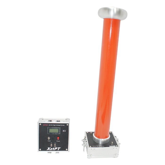
XZT5211 AC DC High Voltage Divider


 中文
中文
 +86-18330222302
 +86-0312-6775757
 sales04@bdhuazheng.com
