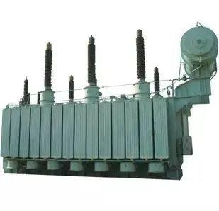
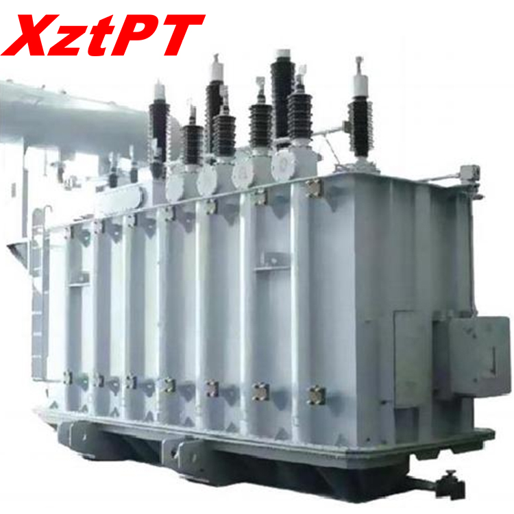
1 structure
The core part of the three-phase oil-immersed transformer is composed of a closed iron core and windings wrapped around the iron core posts. In addition, there are oil tanks, oil conservator cabinets, casings, breathers, explosion-proof pipes, radiators, tap changers, gas relays, thermometers, oil purifiers, etc.
(1) Iron core
The iron core is the magnetic circuit part of the transformer. In order to reduce hysteresis and eddy current losses in the iron core, the iron core is made of silicon steel sheets 0.35 mm to 0.5 mm thick. The surfaces of the silicon steel sheets are coated with insulating paint or surface oxide films are used to insulate the sheets from each other. The upright part of the iron core of a three-phase transformer is called the core column, and the low-voltage winding and high-voltage winding of the transformer are set on the column; the horizontal part is called the iron yoke, which is used to form a closed magnetic circuit.
(2) Winding
The winding, also called the coil, is the circuit part of the transformer and is divided into two types: primary and secondary windings. The winding connected to the power supply is called the primary winding, and the winding connected to the load is called the secondary winding. The primary and secondary windings are made of copper or aluminum wire wrapped with high-strength insulation. The primary and secondary windings of each phase of the three-phase transformer are made into a cylindrical shape and are placed on the same iron core column. The low-voltage winding with a small number of turns is placed inside close to the iron core, and the high-voltage winding with a large number of turns is placed outside the low-voltage winding. This placement is because it is easier for low voltage windings to insulate the core. Sleeves made of insulating material are used to isolate the low-voltage winding and the iron core and between the high-voltage winding and the low-voltage winding to reliably insulate them. In order to facilitate heat dissipation, a certain gap is left between the high and low windings as an oil passage to allow the transformer oil to flow.
(3) Fuel tank
The oil tank is the outer shell of the transformer. The iron core and windings are installed inside and filled with transformer oil. For transformers with relatively large capacity, heat sinks or heat pipes are installed outside the oil tank.
Transformer oil is a mineral oil with good insulating properties. It has two functions: one is insulation. The insulating properties of transformer oil are better than air. Immersing the windings in oil can improve the insulation properties everywhere and avoid contact with air. Prevent the winding from getting damp; the second is the heat dissipation function, which uses the convection of oil to dissipate the heat generated by the iron core and winding to the outside through the box wall and heat pipe. Transformer oil is divided into three specifications: No. 10, No. 25, and No. 45 based on its freezing point. Their freezing points are -10°C, -25°C, and -45°C respectively. They are generally selected according to local climate conditions.
(4) Oil conservator
The oil conservator, commonly known as the oil pillow, is a cylindrical container placed horizontally above the oil tank and connected to the oil tank of the transformer by pipes. The volume of the oil conservator is generally about 10% of the volume of the oil tank. The oil conservator is a capsule-type oil conservator, and the capsule isolates the oil in the oil conservator from the outside air. When the transformer oil thermally expands, the oil flows from the oil tank to the oil conservator; when the transformer oil contracts, the oil flows from the oil conservator to the oil tank. The oil conservator has two functions: first, when the volume of transformer oil expands or shrinks with changes in oil temperature, the oil conservator plays the role of oil storage and oil replenishment, ensuring that the oil tank is filled with oil and the iron core and windings are immersed. in the oil; secondly, it can reduce the contact area between the oil surface and the air, preventing the transformer oil from getting damp and deteriorating.
The oil level display of the oil conservator uses a connecting rod ferromagnetic oil level gauge to observe the level of the oil level. When the oil level is insufficient due to leakage and other reasons, oil should be added in time to supplement it. The oil level gauge is engraved with the oil level height standard lines when the oil temperature is -30°C, +20°C and +40°C, as a standard for oil filling. +40℃ on the oil level mark indicates the maximum oil level of the transformer at the installation site when the maximum ambient temperature is +40℃, and the oil level must not exceed this line; +20℃ indicates the oil level when the annual average temperature is +20℃. Height; -30℃ indicates the lowest oil level line of the no-load transformer when the environment is -30℃. It must not be lower than this line. If the oil level is too low, add more oil. The oil pillow is equipped with a breathing hole to communicate the upper space of the oil pillow with the atmosphere. When the transformer oil expands with heat and contracts with cold, the air in the upper part of the oil pillow goes in and out through the breathing hole, and the oil level can rise or fall to prevent deformation or damage of the oil tank.
(5) Casing
The lead wire of the transformer winding is connected to the external circuit through the guide rod. The bushing is the insulator between the guide rod and the box cover. It plays the role of insulating and fixing the guide rod. There are two types of casing: high-pressure casing and low-pressure casing.
(6) Explosion-proof pipe
The explosion-proof pipe is installed on the transformer tank cover. When a severe sudden failure occurs inside the transformer, the pressure in the fuel tank will rise rapidly to prevent fuel tank explosion accidents caused by excessive pressure rise. After action, the internal pressure of the box is released and the contacts are connected to alarm or trip.
(7) Gas gas relay
Use the flange to install the gas relay between the connecting pipe of the oil conservator and the transformer tank cover. During operation, the gas relay is filled with oil. When a slight fault occurs inside the transformer and bubbles are generated, they will first gather in the upper space of the gas relay. And forces the oil level to drop, causing the upper open cup to lose buoyancy and increase its own mass, thereby deflecting in the opposite direction, causing the magnet to move closer to the reed switch. The principle of lower contact baffle type is the same.
(8) Temperature measuring device
Oil surface temperature rise refers to the value by which the oil surface temperature in the oil tank is allowed to exceed the ambient temperature when the transformer is operating under rated conditions.
The oil temperature of the main transformer body is temporarily set to alarm at 80℃ and trip at 100℃.
(9) Neutral point grounding knife
The neutral point grounding method of my country's 110kV power system mainly adopts the neutral point direct grounding method (including the neutral point grounding method through a small resistance), that is, a large grounding current system. Because when a single-phase ground fault occurs in the system, the ground short-circuit current is very large.
When the transformer is shut down for power supply operation, its neutral point must be grounded. Because the transformer winding is semi-insulated (also called graded insulation), that is, the main insulation of the transformer winding near the neutral point has a lower insulation level than the insulation level at the end of the winding. Therefore, in order to prevent overvoltage from damaging the transformer insulation, when the transformer is shut down for power transmission operation, its neutral point must be grounded.
(10) Tap changer
When the oil conservator is used in an on-load voltage regulating transformer, a capsule-free switch oil conservator is installed at the bottom of the oil conservator.
Transformer voltage regulation methods are divided into two types: on-load voltage regulation and no-load voltage regulation:
On-load voltage regulation means that the tap position of the transformer can be adjusted during operation, thereby changing the transformer ratio to achieve the purpose of voltage regulation.
Transformer taps are generally tapped from the high voltage side. The main considerations are:
(1) The high-voltage winding of the transformer is generally on the outside, and the tap leads out for easy connection;
(2) The current on the high-voltage side is smaller, and the conductor cross-section of the current-carrying part of the lead wire and tap switch is smaller, so the impact of poor contact can be easily solved.
In principle, the tap can be on either side. An economic and technical comparison must be made. For example, the tap of a 500kV large step-down transformer is drawn from the 220kV side, while the 500kV side is fixed.
When the voltage is too low or too high and several taps of the on-load tap-changer need to be adjusted to meet the requirements, the following situations need to be paid attention to:
It should be adjusted gear by gear, that is, every time you press the N+1 or N-1 button, pause for 1 minute. When a new number appears on the gear indicator, press the button again. Repeat the above process in turn until you reach the final goal. When the electric operation is interlocked (that is, one operation will cause more than one tap to be adjusted, commonly known as sliding gear), you should press the emergency button immediately after the second tap position appears on the gear indicator on the main transformer control screen. Stop button and switch to manual operation.
2 Transformer operation and maintenance
In order to ensure that the transformer can operate safely and provide reliable power supply, when an abnormality occurs in the transformer, it can be discovered and dealt with in time to eliminate the fault in the bud to prevent the occurrence and expansion of the accident. Therefore, the transformer in operation must be inspected regularly. Conduct inspections and keep operational records.
(1) Normal operation mode of transformer
①Rated operating mode. The transformer can operate according to the nameplate specifications under specified cooling conditions. The allowable temperature during operation of the oil-immersed transformer should be checked based on the upper oil temperature. The upper oil temperature should comply with the manufacturer's regulations, but the maximum temperature should not exceed 95°C. In order to prevent the transformer oil from deteriorating too quickly, the upper oil temperature should not frequently exceed 85°C.
The external voltage of the transformer should generally not exceed 105% of the rated value. At this time, the secondary side of the transformer can carry rated current. In individual cases, after testing or with the consent of the manufacturer, the applied voltage can be 110% of the rated voltage.
② Overload is allowed. Transformers can operate under normal overload or accident overload conditions. Normal overload can be used frequently, and its allowable value is determined based on the load curve of the transformer, cooling conditions, and the load carried by the transformer before overload. Accident overloading may only be used in accident situations (transformers that are still operational).
The allowable value of accident overload should comply with the manufacturer's regulations; if there are no manufacturer's regulations, the self-cooling oil-immersed transformer can be operated according to the requirements in the table.
(2) Abnormal operation and emergency treatment of transformer
(a) Abnormal phenomena during operation. If any abnormal phenomena are found during operation of the transformer (such as oil leakage, insufficient oil level in the oil pillow, abnormal heating, abnormal sound, etc.), efforts should be made to eliminate them. If any of the following conditions occurs, repairs should be stopped immediately.
① The internal sound is loud, very uneven, and there are popping sounds.
②Under normal cooling conditions, the temperature is abnormal and continues to rise.
③Inject oil into the oil pillow or spray into the explosion-proof pipe.
④ Oil leakage causes the oil level to drop below the limit on the oil level indicator.
⑤ The oil color changes too much and carbon appears in the oil.
⑥ The casing is severely damaged and discharged.
(b) Unallowable overload, abnormal temperature rise and oil level. If the overload of the transformer exceeds the allowable value, the load of the transformer should be adjusted in time. When the transformer oil temperature rises beyond the allowable limit, the cause should be identified and measures should be taken to reduce it. Therefore, the following work must be performed.
① Check the load of the transformer and the temperature of the cooling medium, and check with the temperature that should be achieved under this load and cooling temperature.
② Check the temperature gauge.
③ Check the mechanical cooling device of the transformer or the ventilation condition of the transformer room.
If it is found that the oil temperature is more than 10°C higher than usual under the same load and cooling temperature, or the oil temperature continues to rise while the load remains unchanged, and the cooling device, transformer room ventilation and thermometer are all normal, it may be an internal fault of the transformer (such as Fire in the iron core, short circuit between coil layers, etc.), stop repairs immediately.
If the oil in the transformer has solidified, the transformer is allowed to be put into operation with load, but attention must be paid to whether the upper oil temperature and oil circulation are normal.
When it is found that the oil level of the transformer is significantly lower than the oil level that the oil temperature should be at that time, oil should be added immediately. If the oil level drops rapidly due to a large amount of oil leakage, it is forbidden to change the gas relay to only act on the signal, but measures must be taken quickly to plug the leakage and refuel immediately.
(c) Processing when the gas relay operates. When the gas relay signal operates, the transformer should be inspected to find out the cause of the signal operation, whether it is due to air intrusion into the transformer, a drop in oil level, or a secondary circuit failure. If the fault cannot be detected outside the transformer, the nature of the gas accumulated in the relay needs to be identified. If the gas is colorless, odorless and non-flammable, it is air separated from the oil and the transformer can still continue to operate. If the gas is flammable, the transformer must be stopped and the cause of the operation must be carefully studied.
When checking whether the gas is flammable, special care must be taken not to place the fire close to the top of the relay, but 5 to 6 cm above it.
If the operation of the gas relay is not caused by air intrusion into the transformer, the flash point of the oil should be checked. If the flash point is lower than the past record by more than 5°C, it means there is a fault in the transformer.
If the transformer trips due to the operation of the gas relay and is proved to be flammable gas, the transformer shall not be put into operation again without special inspection and passing the test.
There are generally two types of gas relay actions depending on the nature of the fault: one is a signal action without tripping; the other is both actions at the same time.
If the signal acts but does not trip, there are usually the following reasons.
① Air enters the transformer due to oil leakage, refueling or loose cooling system.
② The oil level slowly drops due to temperature drop or oil leakage.
③A small amount of gas is generated due to transformer failure.
④ Caused by a through short circuit.
If the signal and switch act at the same time, or if only the switch acts, it may be due to a serious fault inside the transformer, the oil level drops too fast, or there is a fault in the secondary circuit of the protection device. Under certain circumstances, such as after repairs, the air in the oil separates too quickly, which can also cause the switch to trip.
(d) Transformer oil leakage treatment
There are two types of oil leakage: weld oil leakage and seal oil leakage. The treatment for oil leakage from welds is repair welding. During welding, the machine body should be lifted out and the oil should be drained out. The cause of seal oil leakage should be identified. If the operation is poor (the sealing gasket is not placed correctly, the pressure is uneven, the pressure is insufficient, etc.), it should be repaired as appropriate. If the gasket is aged or damaged (such as the oil-resistant rubber becomes sticky, loses elasticity, cracks, etc.), the sealing material should be replaced.
(3) Patrol inspection of oil-immersed transformers
Frequent inspections and monitoring of operating transformers should be carried out to detect abnormal phenomena or faults in a timely manner and avoid serious accidents.
Items that should be inspected and monitored generally include:
(1) Is there any abnormal sound from the transformer, such as uneven sound or discharge sound?
(2) Whether the oil level is normal and whether there is leakage or oil leakage.
(3) Whether the oil temperature is normal (the upper oil temperature should generally not exceed 85°C).
(4) Whether the casing is clean and whether there are cracks, damage, discharge, etc.
(5) Check whether the connector is heating.
(6) Whether the explosion-proof membrane of the explosion-proof pipe is complete.
(7) Whether the gas relay leaks oil and whether it is filled with oil inside.
(8) Whether the respirator is unblocked, whether the oil level of the oil-sealed respirator is normal, and whether the silica gel in the respirator has been saturated with moisture.
(9) Whether the cooling system is operating normally.
(10) Whether the shell ground wire is intact.
35kV 20000Kva Oil-Immersed Three-Phase Double Winding Without Excitation Voltage Regulating Power Transformer


 中文
中文
 +86-18330222302
 +86-0312-6775757
 sales04@bdhuazheng.com
