English


1. Ground Resistance
Definition: The total resistance between the grounding device and the earth, reflecting the ability of current to diffuse from the grounding body to the surrounding soil.
Measurement principle: By injecting a test current (usually AC, to avoid polarization effects) into the grounding body, the voltage difference between the grounding body and the auxiliary electrode is measured, and the resistance value (R=U/I) is calculated.
Typical applications:
Verify whether the grounding of power systems (such as transformers, lightning rods) complies with safety standards (such as IEC 62305, GB 50169).
Check the effectiveness of lightning protection grounding and equipment protection grounding.
2. Soil Resistance
Definition: The ability of a unit volume of soil to obstruct electrical current, reflecting the soil's electrical conductivity (unit: Ω· m).
Measurement method: Use the four wire method (Wenner method) to inject current into the soil through four equidistant probes and calculate the distribution of resistivity at different depths.
Purpose:
Before designing the grounding system, evaluate the soil characteristics and determine the optimal burial depth and layout of the grounding body.
Optimize the design of lightning protection grounding network and reduce grounding resistance.
3. Step Voltage and Touch Voltage
Definition:
Step voltage: The potential difference between two feet when a person is walking near a ground fault point.
Contact voltage: The potential difference between a faulty device and the ground when the human body comes into contact with it.
Measurement method: Simulate human impedance model and calculate potential voltage gradient by combining grounding resistance and current distribution.
Safety significance: Evaluate the risk of electric shock to personnel during lightning strikes or short circuits, ensuring that the step/contact voltage is below the safety limit (such as IEEE Std 80).
4. Continuity and continuity of grounding system
Testing content:
Is the connection between the grounding conductor and the grounding electrode reliable (such as welding, bolt fastening points).
The conduction resistance between each node of the grounding grid (usually required to be ≤ 0.1 Ω).
Method: Use low resistance testing mode (such as DC micro ohmmeter function) to directly measure the resistance between conductors.
Application scenario: Check the integrity of large grounding grids such as substations and communication base stations.
5. Ground Impedance
Definition: The obstructive effect (including resistance and inductance components) of grounding devices on high-frequency currents (such as lightning currents and fault currents) in communication systems.
Measurement requirements: A variable frequency grounding resistance meter (such as outputting frequencies above 1kHz) should be used to simulate the actual impedance under high-frequency current impact.
Applicable scenario: Evaluate the lightning current discharge capability of the lightning protection grounding system.
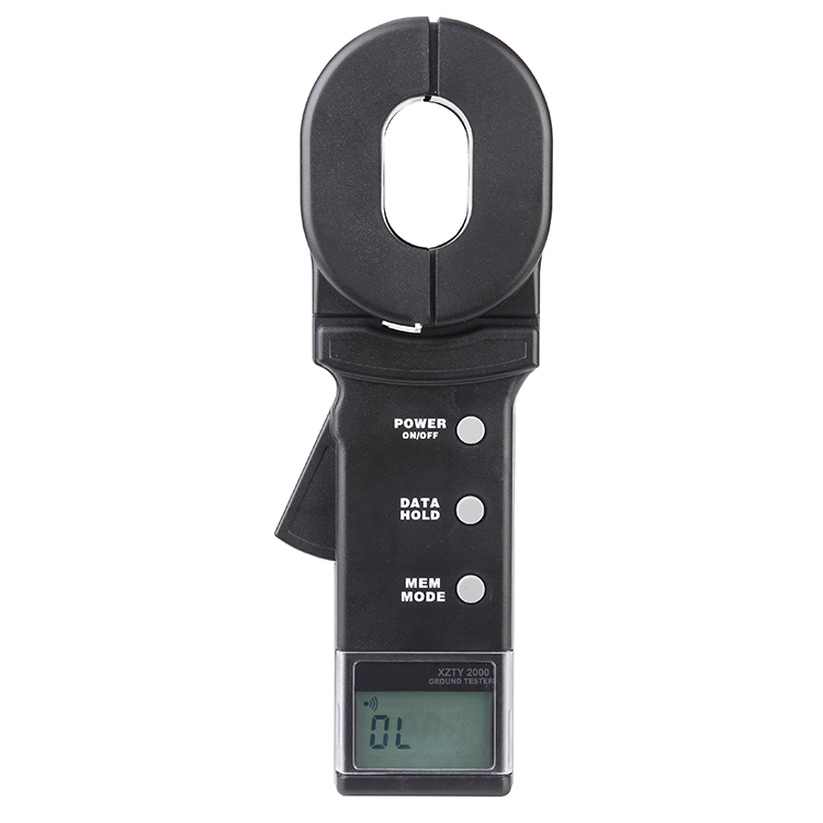
XZTY2000 Clamp Ground Resistance Meter
