
English


HOME >> Products >> Test Equipment
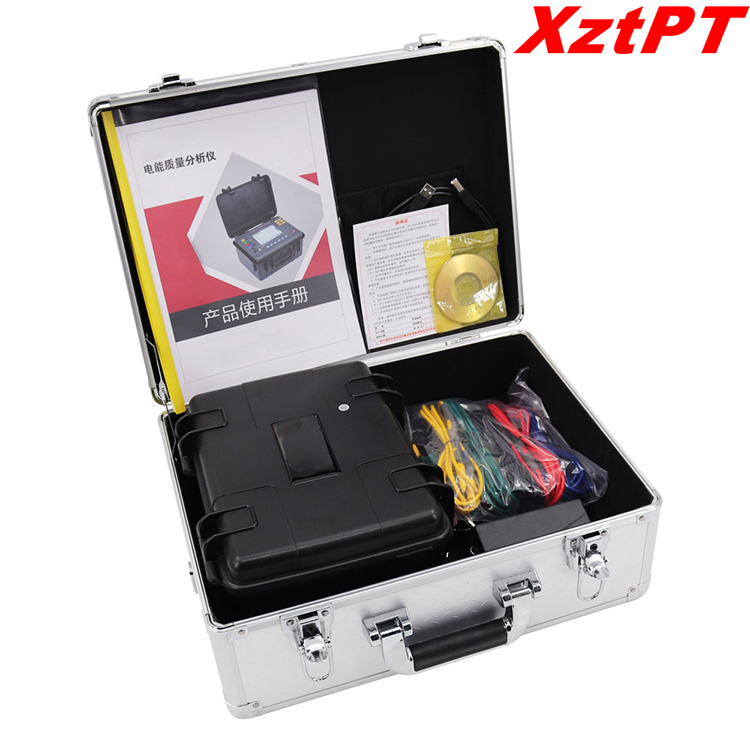
Product Details
Basic Function Introduction
1. Test function:
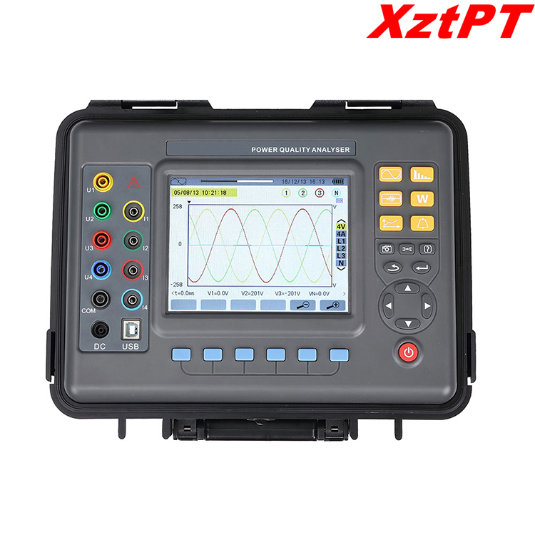
Real-time display of waveforms (4 channels of voltage/4 channels of current)
Voltage and Current True RMS
Voltage DC component
Current and voltage peaks
Current and voltage max/min over time
Phasor Diagram Display
Measurement of harmonics of each phase, up to the 50th harmonic
Bar graph showing harmonic ratio of current and voltage of each phase
Calculation of Total Harmonic Distortion (THD)
Active/reactive/apparent power value and total value of each phase
Active/reactive/apparent energy value and total value of each phase
Transformer K Factor Calculation
Calculation of COSφ Displacement Power Factor (DPF) and Power Factor (PF)
flicker calculation
Three-phase unbalance calculation (voltage and current)
2. Capture and monitor functions:
It can capture and detect the instantaneous changes of grid voltage and current parameters, including voltage and current fluctuations, voltage and current swells, dips, short-term interruptions, transient overvoltages, inrush currents, and instantaneous current and voltage distortions. The instrument can store up to 150 sets of transient waveforms at the same time.
3. Start current monitoring:
It can monitor the inrush current of the line and the starting current when the electrical equipment is started, which is helpful for the correct design of the installed capacity. It can display the rising/falling curve of the effective value of the starting process, the envelope curve of the starting current, and the 4-way current and 4-way voltage waveforms. After triggering, it can record about 100s, and store all current and voltage instantaneous values and waveform curves of each cycle within 100s.
4. Record storage function:
All test parameters of basic test functions (Urms, Uthd, Ucf, Uunb, Hz, Vrms, Vthd, Vcf, Vunb, PST, Arms, Athd, Acf, Aunb, KF, W, VAR, VA, PF, COSφ, TANφ), the 50th harmonic of voltage, the 50th harmonic of current, a total of 123 parameters are recorded, and a trend curve graph is generated, which can record data for a long time as needed. (Select 20 parameters at the same time and record once every 5 seconds, about 300 days can be recorded)
5. Alarm function:
Limits can be set for the selected parameters as required, monitoring whether they exceed the limits, and alarm logs are generated when the limits are exceeded, such as voltage overvoltage, current overcurrent, unbalance exceeding the limit, a certain harmonic ratio exceeding the limit, frequency Over limit, active power over limit, total harmonic distortion over limit, etc., up to 40 groups of alarm monitoring parameters can be set, and each group can be set with different monitoring parameters (including 50 harmonics, a total of 123 different parameters) and limit value to set the minimum time for exceeding the limit. Up to 12800 groups of alarm log records can be stored.
6. Screenshot function:
On any test page, you can take a screenshot to store the current screen, and automatically save the recording time and the test mode you are in. Such as saving current and voltage waves, harmonic histograms, phasor diagrams, etc. Up to 60 groups of screenshots can be saved at the same time
7. Communication function:
The monitoring software can communicate with the computer through USB, and the monitoring software can display the waveform of the power quality analysis test in real time, and can read the detected and captured transient waveform, trend chart record, alarm list, test screenshots, etc.
8. Setting function:
Users can set the time and date, set the contrast and brightness of the display screen, and set the corresponding color of each phase line in the instrument;
The wiring method and grid type of the instrument can be set;
Different current clamps and different voltage test ratios can be selected;
Chinese menu or English menu can be selected.
9. Chinese/English help menu:
At each stage of the operation, you can press the "Help" button at any time to obtain relevant help information.
Technical Specification
1. Baseline and working conditions
Amount of influence | Test items | Baseline conditions | working conditions |
Ambient temperature | all parameters | (23±2)℃ | -10℃~40℃ |
Relative humidity | all parameters | 40%~60% | <80% |
Phase voltage | all parameters | (100±1%)V | 1.0V~1000V |
Line voltage | True RMS value of line voltage | (200±1%)V | 1.0V~2000V |
Current | Measure the current true rms value | (5±1%)A | 10mA~6000A |
Grid frequency | all parameters | 50Hz±0.1Hz | 40Hz~70Hz |
Phase shift
| Active power and active energy | Cosφ=1 | Cosφ:0.2~1.0 |
Measuring reactive power and reactive energy | Sinφ=1 | Sinφ:0.2~1.0 | |
Harmonic | all parameters | <0.1% | 0.0%~100% |
Voltage unbalance | all parameters | <10% | 0.0%~100% |
Instrument operating voltage | all parameters | DC9.8V±0.1V | DC9.5V~10.5V |
External electric and magnetic fields | all parameters | Should be avoid | |
Measured lead position | Measure parameters related to current | The conductor under test is at the approximate geometric center of the jaw | |
2.General Specifications
Power supply | Rechargeable lithium battery pack 9.6V, external charger |
Battery level indicator |
|
Power consumption | The current consumption is 490mA, and the battery works continuously for 10 hours |
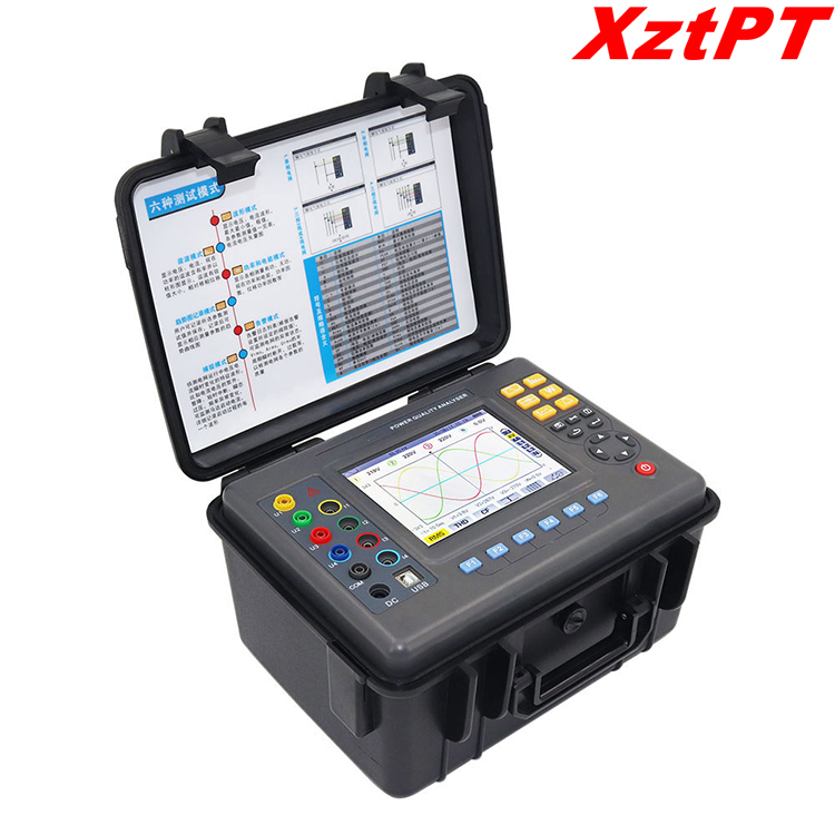
Display mode | LCD color screen, 640dots×480dots, 5.6 inches, display area 116mm×88mm |
Instrument size | Length, width and thickness: 277.2mm×227.5mm×153 mm |
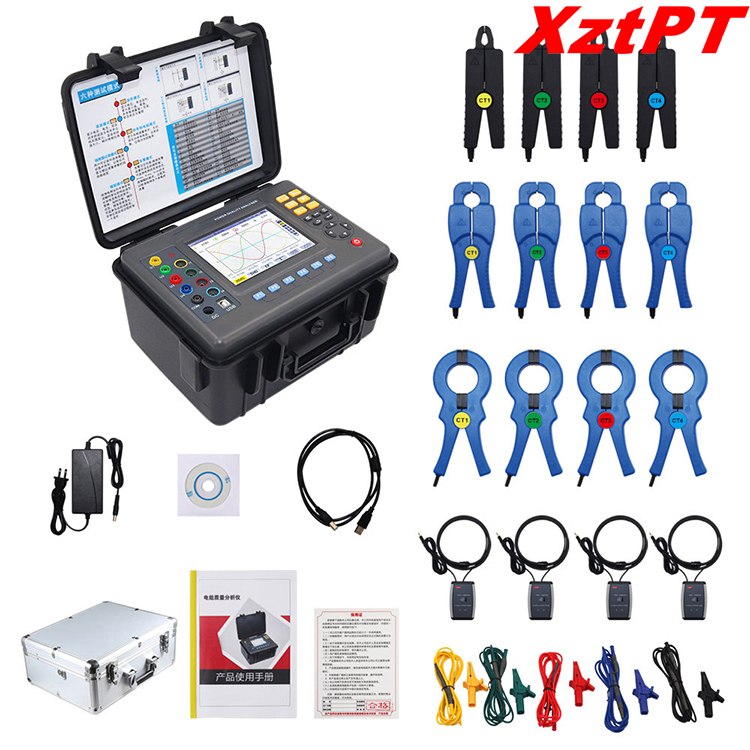
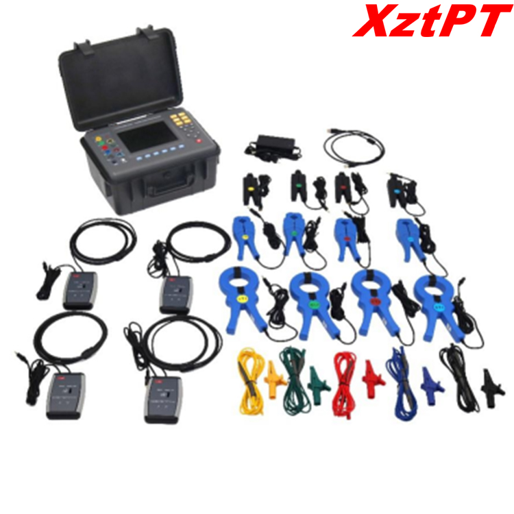
Jaw size | FR008 pointed small current clamp: 7.5mm×13mm (model selection) FR020 round mouth current clamp: 20mm×20mm (type selection) FR050 round mouth current clamp: 50mm×50mm (model selection) |
Number of channels | 4-way voltage, 4-way current |
Line voltage | 1.0V~2000V |
Phase voltage | 1.0V~1000V |
Current | FR008 Current clamp 10mA~10.0A FR020 Current clamp 0.10A~100A FR050 Current Clamp 1.0A~1000A Rogowski coil 10A~6000A Optional transformer, instrument port input current 1mA ~ 500mA |
Frequency | 40Hz~70Hz |
Electricity parameters | W,VA,var,PF,DPF,cosφ,tanφ |
Electric energy parameters | Wh,varh,Vah |
Harmonic | Yes, 0 to 50 times |
Total harmonic distortion | Yes, 0 to 50 times, each phase |
Expert mode | Have |
Transient record group number | 150 groups |
Voltage flicker | Have |
Start current mode | Yes, 100 seconds |
Three-phase unbalance | Have |
Record | 300 days (record 20 parameters at the same time, record 1 point every 5 seconds) |
Minimum& Maximum record value | Yes, the maximum and minimum values within a period of time can be measured |
Alarm | 40 different types of parameter options, 12800 groups of alarm logs |
Peak | Have |
Phasor Diagram Display | automatic |
Screenshot capacity | 60 |
Menu language | Chinese English |
Communication Interface | USB |
Automatic shut-down
| In the alarm/trend graph record/transient capture mode (waiting or in progress), the instrument does not automatically shut down |
In other test modes, if there is no key operation within 15 minutes, it will automatically shut down after 1 minute. | |
Backlight function | Yes, suitable for dark places and night use |
Instrument quality
| Host: 2.41Kg (with battery) |
FR008 pointed small current clamp: 168g×4 | |
FR020 round mouth current clamp: 252g×4 | |
FR050 round mouth current clamp: 463g×4 | |
FR300R Rogowski coil integrator: 280g×4 | |
Test lead and power adapter: 800g | |
Total mass: about 10.8Kg (including packaging) | |
Voltage test lead length | 3m |
Current clamp wire length | 2m |
Working temperature and humidity | -10℃~40℃; below 80%Rh |
Storage temperature and humidity | -10℃~60℃; below 70%Rh |
Input resistance | Test voltage input impedance: 1MΩ |
Pressure resistance | Withstand 3700V/50Hz sine wave AC voltage between instrument circuit and enclosure for 1 minute |
Insulation | Between instrument line and sheath shell ≥10MΩ |
Structure | Double insulation with insulating anti-vibration jacket |
Suitable for safety regulations | IEC 61010 1000V Cat III / 600V CAT IV, IEC61010-031, IEC61326, Pollution Degree 2 |
3.Instrument Accuracy Description (Excluding Current Sensors)
The data below are presented under reference conditions and based on an ideal current sensor (perfectly linear and with no phase shift).
Measurement | Measuring range | display resolution | within the reference range maximum error |
frequency | 40Hz~70Hz | 0.01Hz | ±(0.03)Hz |
Phase Voltage True RMS | 1.0V~1000V | Minimum resolution 0.1V | ±(0.5%+5dgt) |
Line Voltage True RMS | 1.0V~2000V | Minimum resolution 0.1V | ±(0.5%+5dgt) |
DC voltage | 1.0V~1000V | Minimum resolution 0.1V | ±(1.0%+5dgt) |
Current RMS | 10mA~6000A | Minimum resolution 1mA | ±(0.5%+5dgt) |
Phase voltage peak | 1.0V~1414V | Minimum resolution 0.1V | ±(1.0%+5dgt) |
Line voltage peak | 1.0V~2828V | Minimum resolution 0.1V | ±(1.0%+5dgt) |
current peak | 10mA~8484A | Minimum resolution 1mA | ±(1.0%+5dgt) |
crest factor
| 1.00~3.99 | 0.01 | ±(1%+2dgt) |
4.00~9.99 | 0.01 | ±(5%+2dgt) | |
Active power | 0.000W~9999.9kW | minimum resolution 0.001W | ±(1%+3dgt) Cosφ≥0.8 |
±(1.5%+10dgt) 0.2≤Cosφ<0.8 | |||
reactive power Inductive & Capacitive | 0.000VAR~ 9999.9kVAR | minimum resolution 0.001VAR | ±(1%+3dgt) Sinφ≥0.5 |
±(1.5%+10dgt) 0.2≤Sinφ<0.5 | |||
inspecting power | 0.000VA~ 9999.9kVA | minimum resolution 0.001VA | ±(1+3dgt %) |
power factor
| -1.000~1.000 | 0.001 | ±(1.5%+3dgt) Cosφ≥0.5 |
±(1.5%+10dgt) 0.2≤Cosφ<0.5 | |||
Active energy | 0.000Wh~ 9999.9MWh | minimum resolution 0.001Wh | ±(1%+3dgt) Cosφ≥0.8 |
±(1.5%+10dgt) 0.2≤Cosφ<0.8 | |||
reactive energy Inductive & Capacitive | 0.000VARh~ 9999.9MVARh | minimum resolution 0.001VARh | ±(1%+3dgt) Sinφ≥0.5 |
±(1.5%+10dgt) 0.2≤Sinφ<0.5 | |||
apparent energy | 0.000VAh~ 9999.9MVAh | minimum resolution 0.001VAh | ±(1%+3dgt) |
Phase angle | -179°~180° | 1° | ±(2°) |
Tanφ (VA≥50VA) | -32.76~32.76 | minimum resolution 0.001 | φ:±(1°) |
Displacement power factor (DPF) | -1.000~1.000 | 0.001 | φ:±(1°) |
Harmonic ratio Contains 1 to 50 times (Vrms>50V) | 0.0 %~99.9 % | 0.1 % | ±(1%+5dgt) |
Harmonic angle (Vrms>50V) | -179°~180° | 1° | ±(3°) Harmonic 1~25th |
±(10°) Harmonic 26~50th | |||
total harmonic ratio (THD or THD-F)≤50 | 0.0 %~99.9 % | 0.1 % | ±(1%+5dgt) |
Distortion factor (DF or THD-R)≤50 | 0.0 %~99.9 % | 0.1 % | ±(1%+10dgt) |
Transformer K factor | 1.00~99.99 | 0.01 | ±(5 %) |
Three-phase unbalance | 0.0%~100 % | 0.1 % | ±(1 %) |
4.Current clamp characteristics
Current clamp type | Current RMS | Current RMS maximum error | Phase angle φ Maximum error |
FR008 Current Clamp
| 10mA~99mA | ±(1 % + 3dgt) | ±(1.5°),Arms≥20mA |
100mA~10.0A | ±(1 % + 3dgt) | ±(1°) | |
FR020 Current Clamp
| 0.10A~0.99A | ±(1 % + 3dgt) | ±(1.5°) |
1.00A~100A | ±(1 % + 3dgt) | ±(1°) | |
FR050 Current Clamp
| 1.0A~9.9A | ±(2 % + 3dgt) | ±(3°) |
10.0A~1000A | ±(2 % + 3dgt) | ±(2°) | |
Optional transformer | Instrument input current 1mA~500mA | Selected transformer error ±1 % | Selected transformer error ±(1°) |
FR300R Rogowski coil integrator | 10A~199A | ±(1%+3dgt) | ±(3°) |
200A~6000A | ±(1%+3dgt) | ±(2°) |


 中文
中文 +86-18330222302
 +86-0312-6775757
 sales04@bdhuazheng.com
